


 English
 عربى
عربى


NEWS
Home / News / Industry News / How does plasma cleaning work?
How does plasma cleaning work?
Content
- 1 What Happens During Plasma Cleaning
- 2 How Plasma Is Generated for Cleaning Applications
- 3 Chemical and Physical Mechanisms at the Surface
- 4 Comparing Common Plasma Cleaning Configurations
- 5 Inline Configuration of Atmospheric Plasma Equipment
- 6 Model Segmentation and Gun-Head Options
- 7 Materials, Gases and Process Parameters
- 8 Where Plasma Cleaning Is Commonly Applied
- 9 Process Considerations That Affect Cleaning Results
What Happens During Plasma Cleaning
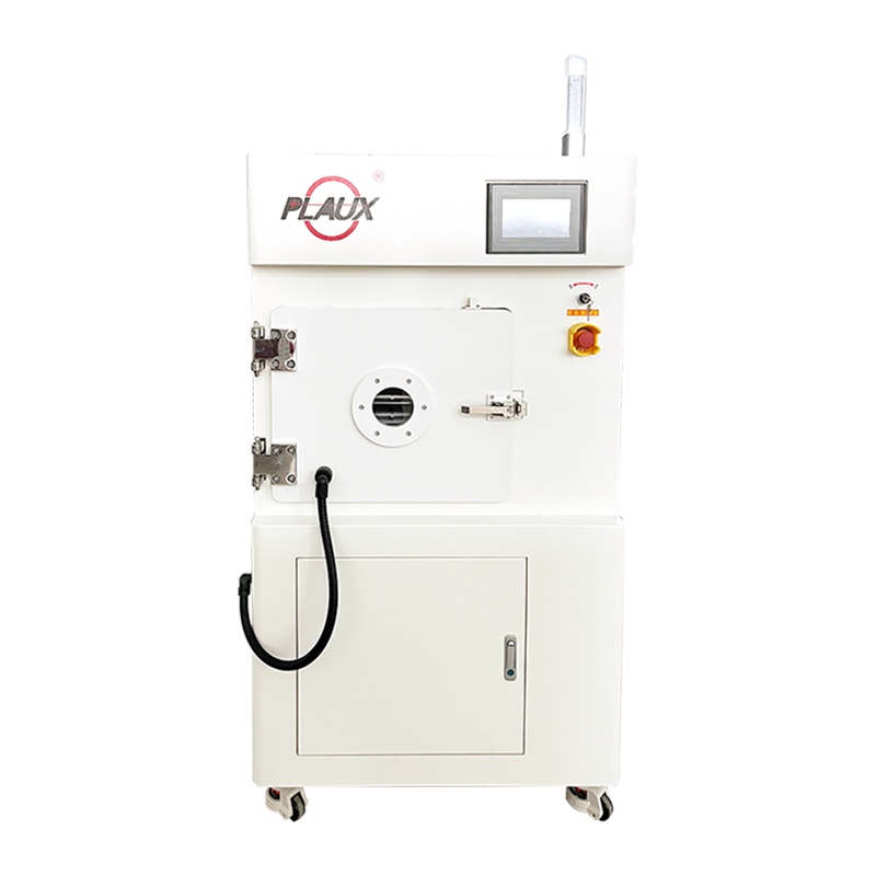
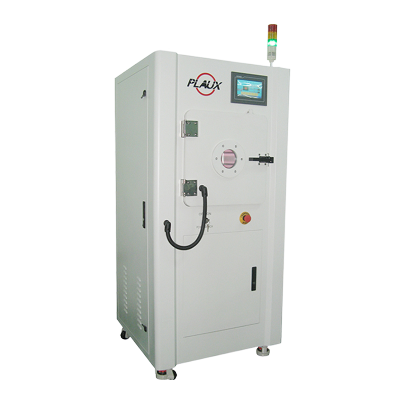
Plasma cleaning removes organic residues, oxide layers and micro-scale contaminants from a surface by exposing it to an ionized gas that contains free electrons, ions, radicals and photons. When a gas such as argon, oxygen or a blended mixture is excited by an electric or radio-frequency field, a fraction of its molecules break apart into charged and reactive particles. These particles collide with the target surface, break chemical bonds in the contaminant layer, and convert the residue into volatile compounds that are carried away by a vacuum pump or exhaust flow. The surface that remains is chemically active and structurally unchanged, which is why a Plasma Cleaning Machine is typically positioned ahead of bonding, coating, printing and soldering steps rather than used as a general-purpose wash.
How Plasma Is Generated for Cleaning Applications
Plasma is often described as a fourth state of matter, formed when enough energy is added to a gas to strip electrons away from atoms. In cleaning equipment, this energy is usually delivered through a radio-frequency generator operating near 13.56 MHz, a direct-current source, or a microwave field, depending on chamber design and the material being processed. The applied field accelerates free electrons already present in the gas, and as these electrons gain speed they strike neutral gas molecules with enough force to knock additional electrons loose. This creates a self-sustaining cascade of ionization inside the chamber, producing a glowing region that contains a mixture of ions, electrons, excited neutrals and reactive radicals. Chamber pressure influences how this plasma behaves: low-pressure systems operating in the range of 0.1 to 10 torr generate a more uniform glow discharge suited to enclosed parts and complex geometries, while atmospheric-pressure systems generate a more localized, higher-density discharge suited to open-air, in-line processing.
Chemical and Physical Mechanisms at the Surface
Two mechanisms act on a surface at the same time during plasma exposure. The chemical mechanism involves reactive species such as atomic oxygen, hydroxyl radicals or fluorine radicals reacting with hydrocarbon chains in oils, fingerprints, mold-release agents and light oxide films, converting them into carbon dioxide, water vapor or other small molecules that leave the surface as gas. The physical mechanism, sometimes called ion bombardment or sputtering, involves charged particles striking the surface with enough momentum to physically dislodge loosely bound particulates and thin films, particularly when argon or another inert gas is used. Oxygen-based chemistries tend to be selected when organic residue removal is the priority, while argon or hydrogen mixtures are selected when oxide reduction or a purely physical cleaning action is preferred. Process duration for many production applications falls between 30 seconds and a few minutes, though the figure depends heavily on contamination type, gas chemistry and applied power.
Comparing Common Plasma Cleaning Configurations
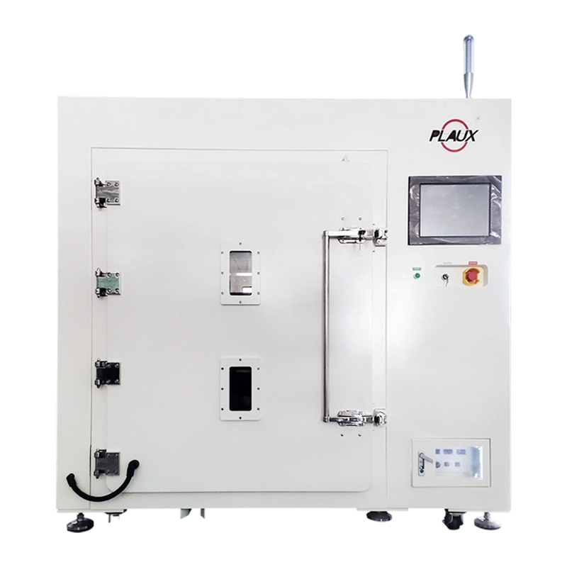
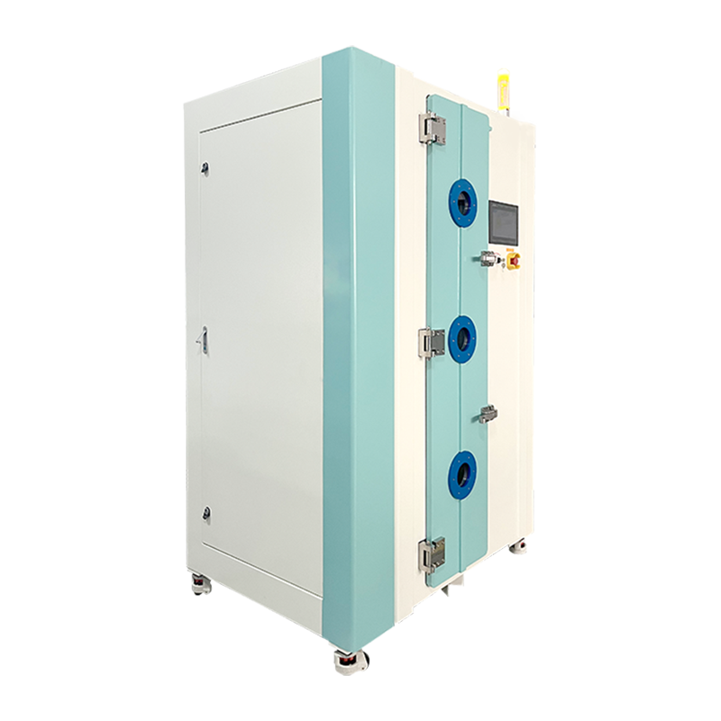
Equipment builders generally offer two broad configurations, and the choice between them depends on part geometry, throughput needs and the level of vacuum infrastructure a facility can support. Low-pressure vacuum systems process parts inside a sealed chamber and are well suited to intricate shapes, porous materials and applications requiring uniform treatment across an entire surface. Atmospheric plasma systems operate outside a vacuum chamber, using a nozzle or array to direct plasma onto a moving substrate, which fits continuous or robotic production lines where cycle time matters more than chamber uniformity.
| Characteristic | Low-Pressure Plasma | Atmospheric Plasma |
|---|---|---|
| Operating environment | Sealed vacuum chamber | Open air, in-line |
| Typical part handling | Batch loading | Continuous or robotic feed |
| Coverage uniformity | Uniform across complex shapes | Localized to nozzle path |
| Common gases | Oxygen, argon, hydrogen blends | Compressed air, nitrogen |
Inline Configuration of Atmospheric Plasma Equipment
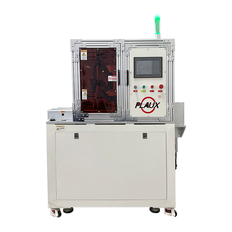
Because atmospheric plasma equipment does not depend on a vacuum enclosure, an atmospheric Plasma Cleaning Machine is often built as a power unit paired with an interchangeable gun head, allowing the same platform to be positioned directly ahead of printing, encapsulation, laminating, coating, welding or dispensing stations on a moving line. One example of this configuration is a plasma power platform built around a phase-shifted full-bridge soft-switching circuit, a topology that reduces switching losses inside the power supply and gives the unit stronger tolerance to grid fluctuation and electromagnetic interference from nearby machinery, which in practice supports a lower long-run failure rate. An analog communication scheme allows individual units to connect to a central control system, so cleaning parameters and run status from multiple machines on the same network can be aggregated and reviewed in real time rather than checked unit by unit, reducing manual inspection workload on a busy line.
Model Segmentation and Gun-Head Options
Atmospheric plasma platforms are commonly segmented into a series of models by power rating, spanning smaller units suited to small-area precision treatment up to higher-power units built for continuous production lines. Within a given series, a higher model number generally corresponds to greater output power, a wider range of compatible materials, and a faster achievable line takt time, while chassis structure and control logic stay consistent across the range. This consistency means a facility scaling up a line, or running several models side by side to cover different part sizes, can standardize operator training and spare-parts inventory once rather than maintaining separate procedures per model. On the delivery end, users can typically switch between a direct-jet head, suited to narrow slots and precision features, and a rotary spray head, suited to larger-area batch coverage, without exchanging the main power unit, since head assemblies are generally modular, optional add-ons.
Materials, Gases and Process Parameters
Process engineers typically adjust four parameters when tuning a plasma cleaning cycle: gas type, chamber pressure or flow rate, applied power, and exposure time. Metals such as stainless steel, aluminum and copper generally respond well to argon or argon-oxygen mixtures, which remove light oxide layers without altering base material dimensions. Polymers and elastomers are frequently treated with oxygen or air plasma, which not only removes residue but also raises surface energy, improving how adhesives, inks and coatings wet the surface afterward. Ceramics and glass are commonly processed with oxygen or a mixed noble-gas chemistry when the goal is residue removal ahead of bonding rather than surface activation. Power levels for many industrial systems fall within a range of roughly 50 to 1000 watts, with smaller values used for delicate substrates such as thin films or flexible circuits and higher values reserved for heavier metal components. For atmospheric-pressure units specifically, the utility requirement is generally limited to dry, oil-free compressed air, which keeps facility installation straightforward compared with systems that need dedicated gas cylinders or a vacuum pump.
Where Plasma Cleaning Is Commonly Applied
Electronics manufacturing relies on plasma cleaning to prepare printed circuit boards before wire bonding, underfill dispensing or conformal coating, since even microscopic organic residue can weaken these connections, and pre-SMT preparation of components follows the same logic ahead of solder paste and flux application. Medical device production uses the process to clean implantable components, surgical instruments and packaging surfaces prior to sealing or sterilization, where surface cleanliness affects biocompatibility testing outcomes. Automotive and aerospace assembly lines apply plasma treatment before adhesive bonding of composite panels, gaskets and trim components, since mechanically fastened or welded joints are increasingly replaced by structural adhesives that depend on strong surface wetting. Packaging operations use plasma to activate plastic films and containers before printing or lamination, allowing ink and adhesive layers to adhere without the addition of solvent-based primers, while pre-weld treatment of metal parts helps reduce oxide films and light contamination that can otherwise affect weld consistency. In each of these settings, the underlying mechanism stays the same even though gas chemistry, power and cycle time are adjusted to match the substrate and the contamination being addressed, and batch-to-batch consistency in this step is generally the property that volume producers are trying to secure when selecting a Plasma Cleaning Machine for a given line.
Process Considerations That Affect Cleaning Results
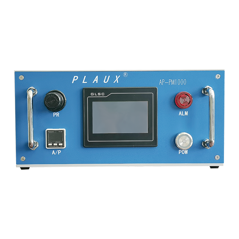
Several variables influence how consistently plasma cleaning performs on a production line. Chamber loading density, or gun-head positioning on an atmospheric line, affects how evenly reactive species reach every part surface, which is why fixtures, racking and travel paths are often designed specifically for a given component geometry rather than reused across unrelated parts. Gas purity matters as well, since trace moisture or hydrocarbon contamination in the feed gas can reduce the concentration of reactive species available for surface reactions. Electrode or antenna condition inside the chamber, or head wear on an atmospheric unit, gradually changes plasma density over repeated cycles, which is one reason many facilities schedule periodic maintenance and requalification of cycle parameters rather than treating initial settings as permanent; standard run-status and alarm indicators on the equipment front panel help flag such drift before it affects a full batch. Surface energy measurements, taken through contact-angle testing or dyne-level test inks, are commonly used after treatment to confirm that a batch of parts has reached the wetting characteristics required for the next bonding or coating step.
PREV:Ultrasonic Welding Machine: The Complete Guide to How It Works, Types & Applications
NEXT:What Buyers Need From Spiral Wound Membrane Element Machine Suppliers and Related Equipment Sources
NEXT:What Buyers Need From Spiral Wound Membrane Element Machine Suppliers and Related Equipment Sources
NEWS
News & Updates
-
In short: an ultrasonic welding machine joins materials by converting high-frequency electrical ener...
READ MORE
 Ready To Customise
Your Products?
-
Kunshan Shifuda Automation Technology Co., Ltd.
-
Quick Links
Home Products About Us Application News Contact Us -
Product Categories
Water Treatment Membrane Filtration Equipment Logistics and Transportation Equipment Medical Consumables Equipment Ultrasonic Welding Machine Non-standard customization Plasma Cleaning Machine -
Contact Us

Mobile: +86 15821087903

Tel: +86 0512-36839705

Email: kellymeng@sfdauto.com

Add:No. 53, Changshun Road, Zhangpu Town, Kunshan City
Copyright © 2026 by
Kunshan Shifuda Automation Technology Co., Ltd.
All Rights Reserved.
Custom Industrial Automation Welding Equipment Manufacturers
